Turn any old PC into a powerful TM Unifi Router. You may be surprised that your old pc is far more powerful than the latest best router!

This article will show you on how to turn a redundant desktop computer into a powerful Fibre broadband router. It works for Malaysia’s Unifi, Maxis Fibre and TIME fibre. Believe me, your old pc may be much better than an expensive router in term of performance.


To give you an idea, an Intel celeron core 2 dual 1.6Ghz with 4G ram can easily supports 300+ connections. An Intel LGA1150 i3 4170 3.7Ghz 8G ram can bring 1000+ connections.

Typical applications are hotel, dormitory, restaurant, office, clubs etc


There are a few things to note before we start:

  1. The guide is easier for those who can understand Mandarin. The software we are going to use is coming from a China company. This company serves Enterprise customers in China. Personal users can use the software for free. The software is called ikuai (爱快) .
  2. This guide uses only simple features of the software, i.e PPPoE. There are many other advanced routing features that I am not familiar with.
  3. For TM Unifi user who has HyppTV box, as usual you will need to use a VLAN switch in front to segregate the VLANs. (refer to https://ahot.home.blog/2019/03/04/tm-unifi-replacement-router-any-router-1-2/).
  4. For Maxis Fibre users, you too, will need a VLAN switch in front to segregate VLAN 621 and VLAN 822.
  5. For TIME users, please connect the BTU directly to this PC that you are going to use it as router (“PC router”)

Preparation :-

  1. An USB drive
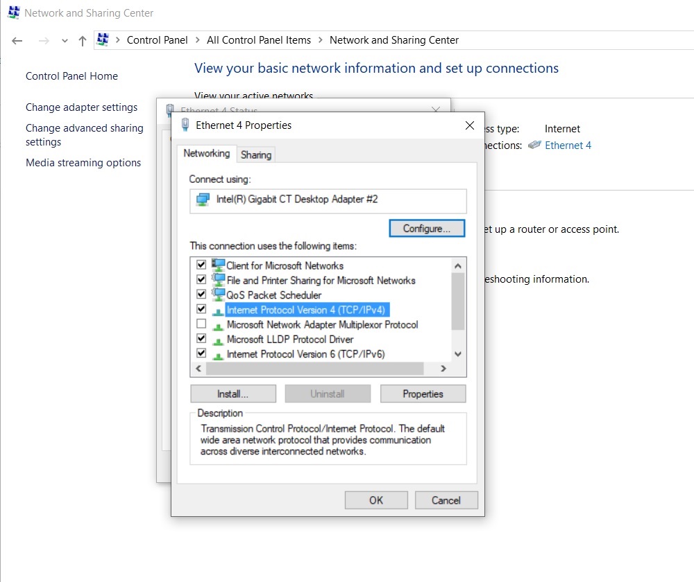
  2. An redundant computer installed with 1 small HDD/SSD and 2 network cards. One of the network card acts as WAN, while the other acts as LAN. Please note that all the partitions/data in that existing HDD/SSD will be wiped at the end of the setup.
  3. Prepare a second computer to access the PC router and do the configurations.

Overall Diagram

For Unifi option 1

Unifi

Please refer to previous posts on the setting up of VLAN switch


OR

For Unifi option 2


Unifi2

For Maxis

maxisMaxis VLAN for internet is 621,  VLAN for Voip is 822.


For TIME

TIME

A) First step is to prepare the installation USB.

Go to www.ikuai8.com

Download the image file and USB writer from there.

You may be experiencing slow down when accessing this china website via google DNS. Try to use default TM’s DNS 202.188.18.188, 1.9.1.9

url

Click 产品( product) , 路由系统 (router OS)

url2

Click 立即下载 (download now)

url3

url4

Click on 64位(64bit) to download IMG image file.

Then, click 新手安装(installation for First Time user)

url5

url6

Click 一键下载(one-click installation)

Unzip the downloaded file.

install1

Next, go into unzip directory “爱快商用路由” (ikuai router) —> “写盘工具” (pen-drive writer)—> “Win32DiskImager.exe”. Double click it to run.

install2

install3

Point the image file to the img file that you have just downloaded. Please take note that the destination to write the img file must be an USB drive. Next, click Write.

The bootable USB is ready.


B) Installation

Insert the USB to the PC router. Set boot setting of the PC router to Legacy boot mode in Bios. Boot from the USB drive.

Ikuai software in the USB will install automatically.

Install4

You will arrive at a screen below. Just press ENTER.

install6

install7

The options in the page are :-

0. System status

1. Network card Binding

2. Set Lan/Wan ip address

3. Set WEB port

4. Ping test

5. Clear firewall rules

6. Reset to system default

7. Reset to default management password

8. Restart / shut down router

9. Network card driver

o. Others option

q. Lock this controller screen

We will only need to set Option 1 and 2.

Note : At any point of time, pressing “q” and ENTER will bring you back to previous menu.


install9

set lan1 and wan1 to the correct “eth”


install8

0. Set LAN1 address

1. Set Wan1 address

q. Return

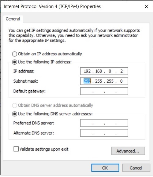
Key in default lan1 ip address of your choice. This will be the default gateway (192.168.88.1 or 192.168.1.1). Connect the setup as the overall diagram above. The hardware installation is done!


C) Software router’s web management.

Use the second computer that you have just prepared to log into this PC router using web browser. Use the ip address you have just set for lan1.  My choice was 192.168.88.1

router1

User : admin , password : admin


router2

This is the first page you will see. If you wish the page to be displayed in English, you will have to use chrome web browser to translate the page (right click on the empty space and click translate). However. the translation is not accurate.

Example of translated pages as below :-

unifi direct3

unifi direct4


Next, click 网络设置 (wan setup)

1

click 内外网设置(internal and external network) , select the network card you had tied to wan1, click 绑定(binding).    If you see 解绑,it means UN-binding. You have to make sure it is bound.

1a

Click on the wan1 icon

2

Select ADSL/PPPoE,  key in your Unifi account’s user and password. Leave other settings as default. Hit connect.

Note : For user without hypptv, you can actually use 混合VLAN模式 (VLAN mix mode),set VLAN 500 here and skip the VLAN switch that is sitting in front. You can connect the BTU directly to the PC router!


unifi direct2


unifi direct1


3

You are connected to Unifi using a PC!


Next, we go to other settings

4

DHCP settings.  添加(add)

6

Add a DHCP server at lan1

7

You can also make an auto-assigned ip to become fixed ip.


Enable or disable UPnP.

8

It is advisable to leave UPnP disable.

9

Port forwarding. Click 添加(add)

10

内网地址 – internal ip

内网端口 – internal port

协议 – protocol

外网地址 – external address, 全部 (all)

外网端口 – external port

备注 – name / remark

保存 (save)

取消 (cancel)

That’s all for the settings you need.


The END


TM Unifi router replacement – Any router (1/2)

Today, I am going to share a setup which fully works with TM Unifi and at the same time provides enough LAN ports.

This setup virtually makes all old routers to support Unifi,any router that can do PPPOE. It also works with china-brand routers. Imagine, you can now use all the routers from taobao. Use any routers listed in a “路由器” (router in chinese) search.

12


The switch I use in this setup is TP-LINK (T1500G-8T)/(TL-SG2008) JETSTREAM SMART SWITCH . It supports a complete lineup of layer 2 features, including 802.1Q tag VLAN. It is available from 11street, lelong, shopee or lazada Malaysia, @ RM270.

Untitled

t1500g-8t


Lets begin with overall diagram.


main


Firstly, go to Network and Sharing Center, change your current Ethernet properties TCP/IPv4 as 192.168.0.2

ethernet properties

ipa

Choose a port to connect from your pc to the switch. Use port 1 because you will only have port 1 as VLAN 1 untagged at the end of this setup and web management of this switch needs VLAN 1.

Log in to the switch (192.168.0.1 if you leave it as default). Both user and password are admin. Go to L2 Features, VLAN, 802.1Q VLAN, VLAN Config. Click Add and get VLAN 500, VLAN 501 and VLAN 600 as below:-

5a

2

3

4

VLAN 501 is just an VLAN ID that I choose to represent the packets coming out from authenticated PPPOE. You can name it to any number you like from 2 to 4094. Save settings after this.

10

Next, go to port config. Get the all the PVID for untagged ports as shown, apply and save settings again.

5

Next, configure IGMP Snooping on the switch. With IGMP Snooping, the switch will forward IPTV stream only to the ports that request the IPTV service rather than to all ports. This is to avoid multicast traffic to flood the traffic to all the ports.

6

7

Leave “Forbidden Router Ports” as default.

9

Apply and save settings.

Next, connect all the connections according to the overall diagram. Connect the Telekom’s Broadband Termination Unit (BTU) to the switch. Make a connection from port 2 of the switch to WAN of your router and a connection from your router’s LAN port back to port 3 of  the switch. Connect your PC or Wireless Access Point to the ports with VLAN 501.

Log in to your router ip and put in PPPOE user and password. That’s it!

I choose to change the default ip of the switch and its management VLAN ID to 501 as shown below (my router ip is 192.168.88.1). It will be easier for me to manage the switch in future. I can manage it from any port with VLAN 501. You may choose to use default settings but you have to use port 1 of the switch whenever you want to access to the web config of the switch.

1

The end (1/2)

Note: Always Untag ports that have non VLAN aware devices – like computers and printers. Tag ports to VLAN aware devices – like phones, access points, other switches (this is how you VLAN trunk between switches), etc.


TM Unifi router replacement – Trunk port (2/2)

I am having a problem. The location of TV is far away from the room where BTU is located (BTU room). There is only 1 LAN cable connecting between these 2 locations.

I want to watch HyppTV programs in living room and play movie files from NAS (located at BTU room). The player is an android box near to my TV.

I will use 2 pcs of TP-LINK (T1500G-8T)/(TL-SG2008) JETSTREAM SMART SWITCH. This method is to trunk both Internet and HyppTV packets from switch 1 to switch 2 in living room.

main2


Let’s begin with the first switch.

The only difference for the first switch is at port 8. The rest of the settings are identical as in guide 1/2.

10

11

Remember to set VLAN 501 at port 8, tagged.

sw1

Then, set the PVID.

12


Second switch

1


2


3


4


Then, set PVID for second switch.

5

Set the all the settings of IGMP snooping same as first switch

6


7


8

It is done! The HyppTV is available at port 8 of second switch. If you have 2 unifi Set-top-box, you can actually make small tweak to port 7 of switch 1 and watch TV at the location of switch 1.

Thanks for reading. Click like if you find this post useful.

Make Any Mesh WiFi a TM Unifi replacement router. TM Unifi router replacement.

I would like to share with you on how to replace Malaysia’s TM Unifi’s router with a switch. You can use any router to support both Unifi Internet and HyppTV. This applies to any third party routers with or without VLAN tagging. It is best suited with Mesh Wifi router like TP-link Deco, Asus Lyra, Huawei Q2 etc. This setup is useful for Mesh Wifi because it normally comes with just ONE outgoing port.

Let’s start with the overview of the setup.

3

I will use Asus Lyra as the example. Asus Lyra has VLAN tagging, but it has only one outgoing port. If you want to use it as router mode, you will either lose Internet or HyppTV. We will overcome this by using Netgear GS105E or GS108E. GS108E is 8 ports version. GS108E was tested not working.

l_10174860_001

To set Asus Lyra as router mode, Incoming cable from BTU will have to use the LAN port near to the power port. For Deco, please refer the TP-link user manual to identify which port to be used as incoming.

Firstly, set the Lyra as router mode and turn off any VLAN tagging. This means that you won’t be using any TM Unifi profile in settings.

q8

Then, complete the PPPOE , WiFi and other settings as usual.

q9

Referring to my previous post on setting up GS105Ev2, you will get all the settings as below.

q2

q3

q4

q5

q6

q7

VLAN 501 is up to your choice, any number from 2 to 4094. It is to represent the packets from authenticated PPPOE. After the config is done. Please refer to the initial diagram above and do the physical connections. You can have Internet and HyppTV up and running now.

How to connect TM Unifi and HyppTV from router location to another location with a single LAN cable. (Asus RT-AC88U + Netgear GS105E)

I would like to share with you my TM Unifi setup at my home. Below is my scenario:-

I wish to have both Hypptv and internet at the a location where it is far away from my Fibre modem and router. There is only one physical LAN cable connecting from the router location to the place where I wish to have HyppTV (iptv) and Internet connection. This is made possible by VLAN trunking.

I use Asus RT-AC88U and 2 pieces of Netgear GS105Ev2. You may use any other Unifi supported router and any switch that has VLAN support for traffic segmentation.

3a

1st stage – Preparation-:-

Setup your router as usual. Identify the router’s default port for IPTV. For Asus RT-AC88U, it is LAN4. Complete all the router settings. Make sure that PPPOE is working.

router

Skip the below step to 2nd stage if you do not wish to change the default IP


Go to Network and Sharing Center, change your current Ethernet properties TCP/IPv4 as 192.168.0.x

ethernet properties

ipa

Power on GS105Ev2 and connect a LAN cable directly from your pc to the switch. GS105Ev2 has default ip 192.168.0.239. Login password is “password”.

Change the default ip of switch

For easier access from existing network, I would change GS105Ev2’s gateway to Asus router IP, and set the LAN IP ip of the switch to be the same network. Thus, we can manage it from the router network without making direct connection to the switch every time you want to access.

GS105Ev2 settings

DHCP : Disable

IP : 192.168.88.31 , subnet : 255.255.255.0

Gateway address : 192.168.88.1 (follow your router’s IP)

Apply settings. If you encounter anything wrong when changing the default ip of the switch, just reset it and retry.

S1

Restore and change the your computer’s TCP/IPv4 settings back to normal as before.

6a

Connect GS105Ev2 from the router network, 192.168.88.31


2nd stage – Switch A

Go to VLAN → 802.1Q → Advanced →VLAN Configuration → Enable

At the VLAN ID , key in 501 at the VLAN ID box and click Add. This will add VLAN 501 (you can choose any VLAN number from 1 to 4094). This VLAN is named for the authenticated PPPOE. It has local network access and Internet. We will connect this LAN to Port 1 of switch A.

Add VLAN 600 and apply setting.

s2

Go to VLAN membership, select VLAN ID that you want to edit. Click on the port multiple times, it will rotate between “T” for tag , “U” for untagged and blank. Get the all results below. Be sure to apply setting for each VLAN before going to next VLAN.

s3

s4

s5

As a good practice, allow only one untagged VLAN for a port only. Be sure to configure the PVIDs for Untagged ports and that they have matching VLANs. Go to the Port PVID, click on the port, change the PVID as below and Apply.

s6

Go to System → Maintenance → Device Reboot → click the Check box → Apply. Restart switch A.

3rd stage – Switch B

My Switch B has the similar default IP changes as Switch A.

t1

Using the same method of 2nd stage steps, you will end up the settings as below for Switch B.

t2

t4

t5

t3

t6

Reboot Switch B and connect cables according to the first diagram. It is done! You are now able to trunk two different VLANs into one physical RJ45 cable.

All the untagged ports with VLAN501 in Switch A and B ( port 3, 4 of Switch A and 2, 3, 4 of Switch B) are having Local access and internet connection. You can play the movie files from NAS connected to router from any of these ports.

Note: Always Untag ports that have non VLAN aware devices – like computers and printers. Tag ports to VLAN aware devices – like phones, access points, other switches (this is how you VLAN trunk between switches), etc.

Edit : A reader, Nicholas, has pointed out that it is best to use default VLAN 1 on both switches. Thus, VLAN501 is unnecessary. I agree with him.

You can choose to do the setup as above or just do the VLAN600 settings, leave other ports as default. The default vlan is 1 untagged.